
Light Blob Detection with $5 Camera
November 30, 2015
Overview
For this project I tried to get an Omnivision 7670 camera working with various microcontrollers in order to detect light blobs. I ran firmware in C on Arduinos and the Particle Photon, as well as code on the computer to display the video stream in Processing.
I succeeded in that I could detect blobs of light. But I was not successful in getting quality images or video stream from the camera.
STATUS: Not maintained.
Please don’t contact me about this project, unless you know how to make it work better.

The Omnivision OV7670 camera is a cheap, mobile-phone quality CMOS camera that in bulk sells for under $5 from Chinese suppliers on Alibaba. The camera is supposed to be able to stream VGA 640x480 resolution video at 30 frames per second. There are different libraries and projects written online to interface this camera with various microcontrollers, including Arduinos. The camera can take 3.3V input, and some online claim that 5V input may burn the image sensors.
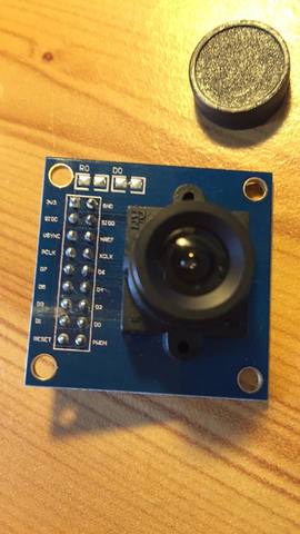
In the States, one can buy a PCB module for this camera for $8-25 on Amazon that is is 3.5mm x 3.5mm x 3mm deep. The module comes in 2 forms: with a memory chip or without. It also comes in different form factors in the number of pins: 18, 20, 22, and 24 pins. This module breaks out and labels the camera’s pins to male headers that can be soldered, or plugged into female/male ports for breadboarding. In addition, the module comes with a case that is much larger than the actual camera itself, with a removable camera cap. One can manually adjust the focus of the camera by screwing it left/right.
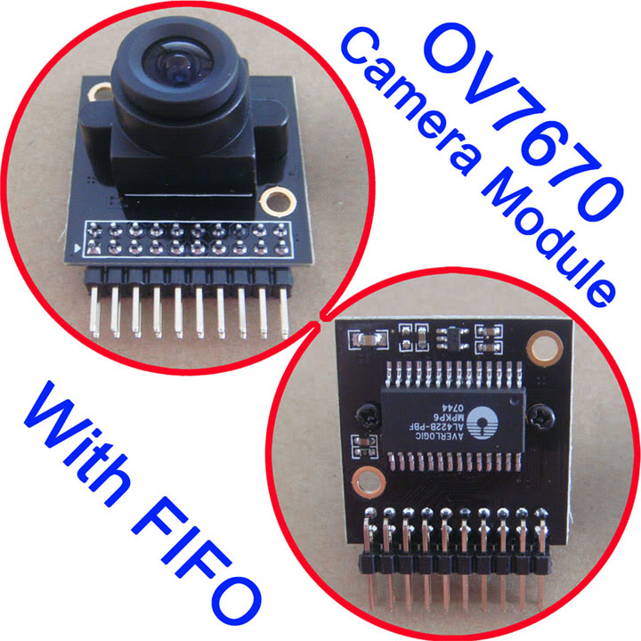
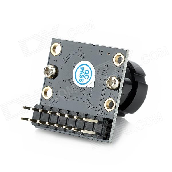
To determine whether the OV7670 camera module has a memory chip or not, turn it over; the one with “FIFO” memory has a little horizontal memory chip (ALB422) on the back.
…while the OV7670 non-FIFO does not have it.
The one with a memory chip (ALB422) has enough space to store 1 image in raw Bayer image format, at 1 byte/pixel (more on YUV image format below, under “Image color formats”). It can hold 384K bytes (while 640px * 480px * 1 byte/px = 307.2K bytes). The module then allows the image to be read from the memory chip off 8 parallel data pins. I believe more data from a higher quality image can be taken with the camera, but it can’t be stored and must be read immediately or the data will be lost.
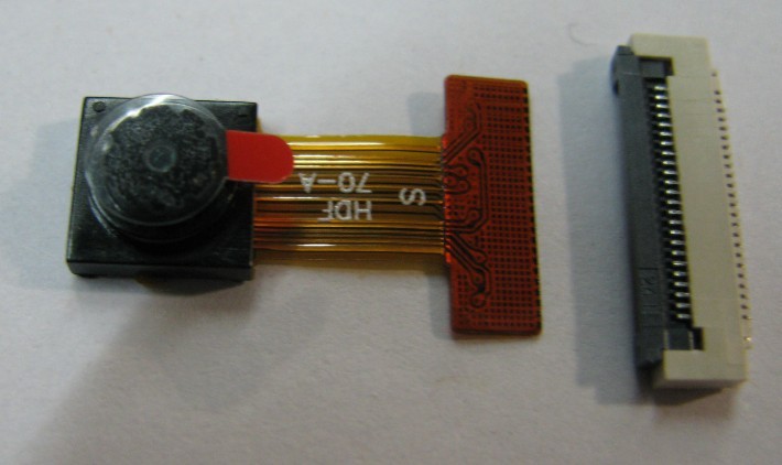
This camera module makes prototyping with the camera quite easy. But in the case of manufacturing, the bare camera often comes with “Golden Finger” connections for each pin. Without the bulky case of the module, the form factor for the actual camera is quite small:
Implementation
I tried various microcontrollers with the OV7670 with FIFO, including different Arduinos and Arduino clones:
-
Nano
-
Mega2560
-
Mega clone
-
Pro Mini
-
Particle Photon (Arduino-code compatible microprocessor with a built-in WiFi chip and online IDE).
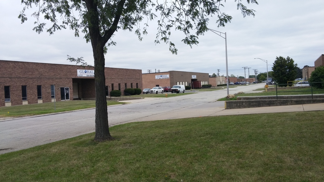
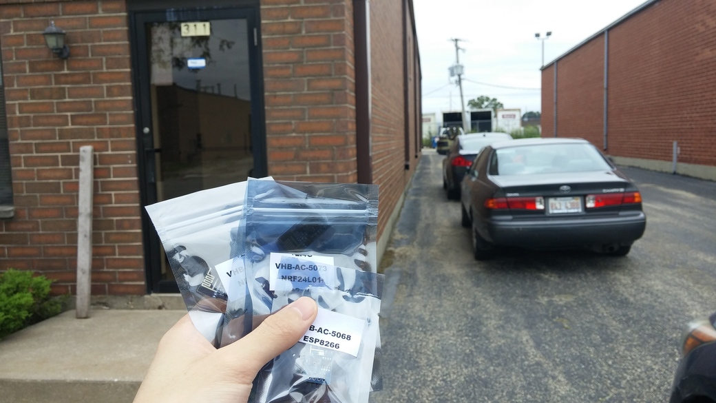
I bought many of my Arduino clones from ValueHobby, a warehouse/store near Chicago O’Hare Airport which sells very cheap Arduino clones and other electronic components from China in the $2-5 range. From Northwestern, ValueHobby is a 40 minute drive, and they offer standard ground shipping (probably 3 days). I couldn’t wait so I drove there to pick up my parts the day I ordered them.
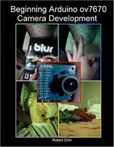
Fortunately, someone wrote an entire book on how to use the OV7670 + FIFO camera, with the Arduino Mega2560. This book can be bought on Amazon for ~$20. It uses the version of the OV7670+FIFO that has 22 pins. It contains a library for the register settings to make the camera work, explanation of its components and timing diagrams, tips for coding with the Arduino, as well as code for taking a picture and storing it in an SD card connected to the Arduino. The book’s website is in “Sources” below.
I also heavily leaned on code from a repo called Arduvision (see “Sources” below). It uses the version of the OV7670+FIFO that has 18 pins (the “missing” pins, in comparison to the 22 pins of the OV7670 from the book code, are not used anyway. More on that under “Pins” below). The code is supposed to read a live stream of the camera feed, send it over Serial USB to the computer, and, with code for an IDE called Processing, display light blob tracking as well as live video. The light blob tracking code worked but the live video and images did not.
Lastly, Becca Friesen had worked with the non-FIFO camera on a PIC32MX microcontroller for finger detection, and she shared her writeup. I also worked with my classmate Athulya Simon, who tried to connect the OV7670 + FIFO camera with a PIC32MX, in order to drive a robotic car. I also had help from Spencer Williams debugging the SD card reader.
Technical Details
Register Settings
There are many registers for this camera, and many register functions have multiple registers and register values. A comprehensive list of each register and bit can be found in the datasheet listed in the Sources section of this page. The hard way to change registers is to write functions to change a bit and mask the others; the easy way if you’re using an Arduino is the write function from its Wire library (see examples from the book code in “Sources”). In addition, libraries for the register settings can be found in the code from the book as well as some of the repos in the sources.
Registers are read and set by the I2C data line (SDA), and the clock pulse to the camera is supplied on the I2C clock line (SCL).
Resolution
The OV7670 camera has several options for resolution:
-
VGA (640x480 pixels)
-
QVGA (320x240 pixels), 1/4 the size of VGA
-
QQVGA (160x120 pixels), 1/16 the size of VGA
-
and weird resolutions like CIF (352x288 pixels) and QCIF (176x144 pixels).
Image format
Image output formats can be changed from the register settings. The OV7670 can output various quality RGB, YUV, YCbCr, and Raw and processed Bayer formats. They will be covered more in detail below in “Image color formats.”
Frames per second
The camera uses a clock to scale the frames per second. The max is 30 fps.
Other settings
In addition to setting the resolution, image format, and frames per second, the camera also has other neat register settings. These include:
-
Exposure - the amount of light the image is exposed to over time; the more exposure time, the brighter the image.
-
AEC (Auto Exposure Control) settings
-
Gain - Some photographers compare this as the electronic analog to focus, when the signal is amplified electronically. An image with more gain has more luminance in the photo.
-
AGC (Auto Gain Control) settings
-
White balancing - calibrating the “white point” of a photo. Depending on the lighting conditions, a pure white wall for example may seem off-white in the image. This lighting condition may throw off all the colors. By finding a constant red, green, and blue correction to calibrate the off-white as actual white, this correction may be applied to the rest of the pixels so that all colors may be shifted toward their actual color values regardless of the situational lighting condition.
-
AWB (Auto White Balancing) - auto-sets the whitest point of a photo to find the above correction
-
BLC (Black Level Calibration) - same as white balancing above, but for black
-
ABLC (Auto Black Level Calibration) - calibrates the blackest part of the image to true black, and corrects the rest of the colors
-
NightMode - not entirely sure how this works, but it allows the camera to work in low light conditions. Perhaps it changes the exposure and gain settings.
-
Demosaicing - processing the Raw Bayer image format into full color image (see below in “Image color formats”)
-
50/60 Hz detection - Eliminate flickering in the camera’s video from common fluorescent lights that run at 50 Hz, or monitors and screens that run at 60 Hz. Presumably the camera does this by dividing frame-rate or shutter speed by a constant to sync with the lighting pulse rate.
-
Other register settings, such as edge enhancement, denoising, image scaling, saturation, vertical/horizontal flipping, and other color correction (using gamma curves and histograms). There are also many registers whose functions are not explained, as well as unused register bits.
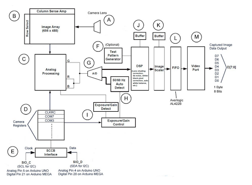
Camera components:
Here is how the camera works. First, light hits the lens (A) and is fed into the image array (B), which is slightly larger than 640x480 (it’s 656x488 - not sure why). The image array is covered by red, green, and blue sensors that only allow those parts of the wavelength in, arranged in a raw Bayer format (see below under “Image color formats”). The image array transmits an analog intensity for each sensor.
The first step in processing is analog processing (C), where AEC, AGC, ABLC etc. are applied. These settings can be automatic or manual, depending on the register settings (most likely they will be on automatic, for ease of use). Then other register settings (D) such as resolution, image format, frame rate etc. are called. These registers are read and changed from the SCCB interface (E) which is connected by I2C to the processor. There is also a register setting option of generating a test pattern (F).
The next step in processing is that the analog signal is converted to a 10 bit digital signal by an ADC (G). Settings such as 50/60 Hz Auto Detect (H) and exposure/gain detection and control (I) are utilized, followed by a DSP (digital signal processor) (J) that handles white balance and color correction such as gamma control, saturation, and de-noising. This is also where a color matrix is applied to convert colors if needed, with a fixed formula multiplying RGB values by a conversion matrix set by camera registers to return YUV values, for example (see “Image color formats” below). The last processing register is an image scaler (K) that scales down VGA quality to the other available resolutions.
The image then goes into the FIFO memory buffer (L), which as explained above can store 1 VGA-resolution image at 1 byte/pixel in raw Bayer format, or lower resolution images at higher byte/pixel in other formats. Finally the image can be read out of the 8-pin video port (M) through pins D0-D7, at 1 bit/pin at a time, for a speed of 1 byte/read cycle from all the pins.
Pins:
-
3V3 —– input supply voltage (3V3)
-
GND —– ground
-
SIO_C (aka SIOC) —– SCCB interface control clock (Same/compatible with SCL on I2C. MAY NEED PULL-UP RESISTOR ON 5V MCU)
-
SIO_D (aka SIOD) —– SCCB interface serial data (Same/compatible with SDA on I2C. MAY NEED PULL-UP RESISTOR ON 5V MCU)
-
VSYNC —– frame synchronizing signal (input - pulses at beginning and end of each frame)
-
HREF —– line synchronizing signal (UNUSED)
-
D0-D7 —– data port (input)
-
WEN (aka WR) —– write enable to memory (output)
-
RST —– reset port (triggered when LOW, UNUSED)
-
PWDN —– power selection mode (triggered when HIGH, UNUSED)
-
STROBE —– camera flash control (UNUSED)
-
RCK (aka RCLK) —– FIFO memory read clock control terminal (output)
-
OE —- FIFO off control / “output enable” (connect to GROUND RAIL)
-
WRST (aka FIFO_WRST) —– FIFO write pointer reset terminal
-
RRST (aka FIFO_RRST) —– FIFO read pointer reset terminal
Pin connections
The camera’s SCCB protocol is the same as I2C. So the SIOC and SIOD pins should be connected to the I2C pins of the microcontroller (SCL and SDA respectively).
3V3 should be connected to an input voltage of 3.3V, and GND should be connected to Ground.
Some pins like HREF, STROBE, RST are unused, while OE should be connected to GND.
My guess for why they are unused: OE (output enable) should always be pulled low (connected to ground). We don’t need a STROBE light for our application. HREF for row synchronization may be redundant if we know the resolution from the register and have VSYNC for the start/end of the frame. RST is subsumed for our purposes by WRST and RRST. PWDN is also unused as you can just end the program or disconnect the device to power down.
The rest of the pins can be connected to GPIO pins, mostly set as output. If your board doesn’t have enough digital pins, you can of course connect them to Analog pins. Data comes in parallel from the eight D0-D7 pins.
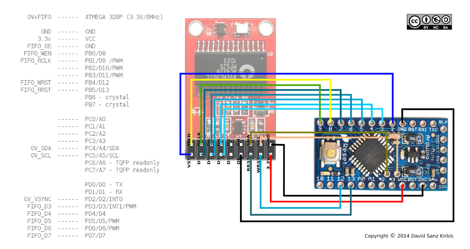
Here is an example of pin connections, using the Arduino Pro Mini. This is from the Arduvision code. Note that it doesn’t use all the data pins (leaves the three pins D0:D2 unattached) and gives up some quality for faster processing.
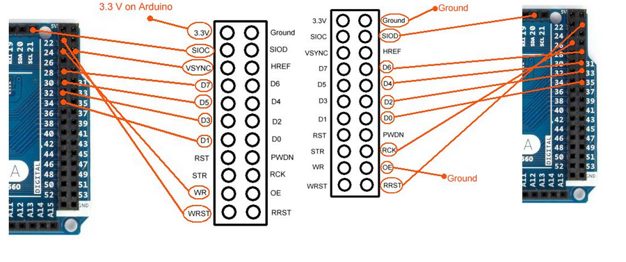
Here is another example of pin connections, using the Arduino Mega 2560. This is from the book code. It uses all 8 data pins.
Here, the Arduino Mega 2560 is also connected to an SD card reader by the SPI protocol. Different Arduinos have different dedicated pins for interfacing with SPI; on the Mega 2560 it was 51-MOSI, 50-MISO, 52-SCK, 53-SS (not shown in the image below).
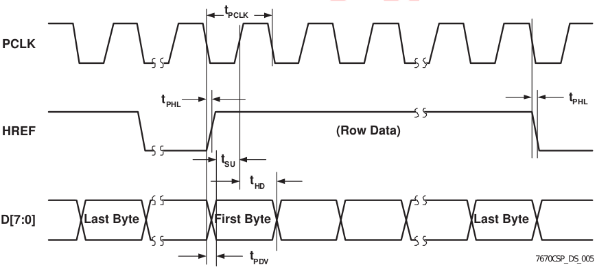
Timing diagrams:
Here is how the timings work. Different pins must be brought to high or low to read image bits from the camera sensor, write them to the FIFO memory chip, and then pull them off of the memory chip onto the microprocessor. Below is the sequence for one frame.
-
At the beginning of the frame, VSYNC is pulsed high, then returns to low.
-
Next, Write Reset must be reset to low to indicate the beginning of the frame.
-
Then, Write Enable must be set to high to allow the image to be written to the memory.
-
Data bits are written, one by one and line by line, to the memory.
-
VSYNC is pulsed high again to signal the end of the frame.
-
Finally, Write Enable must be set to low to stop writing any more data to memory.
-
To read from memory, Read Reset must be reset to low to indicate the beginning of the frame.
-
Each clock cycle from RCK reads 1 bit from each of the 8 data ports, meaning up to 1 byte is read in total each cycle.
VGA output:
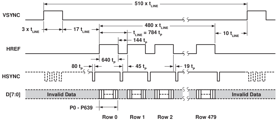
Image color formats
There are several different options for image color formats outputted by the camera. These are versions of RGB, YUV, YCbCr, and raw/processed Bayer.
-
The RGB formats used by the OV7670 are the RGB565, RGB555 and RGB444.
-
The numbers correspond to the bits used to store each color, for one pixel. For example RGB565 uses 5 bits for R, 6 bits for G, and 5 bits for B.
-
In addition there are formats with Y (luminance), such as YCbCr and YUV. In these formats, the Y itself is the black and white version of the image, while the other values add color. The UV from YUV are from a color plane, while CbCr refer to blue and red components.
The following function can convert YCbCr to RGB:
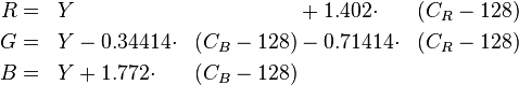
Specifically, the OV7670 uses a YCbCr422 format. This is a strange format where 1 byte is given to Y, Cb, and Cr each, which makes it seem like each pixel is 3 bytes. But two consecutive pixels share the same Cb and Cr values. So for two pixels, there are only four values, Y1, Y2, Cb1, Cr1, which is 4 bytes per 2 pixels, or an average of 2 bytes/pixel.
Finally, there is the Raw Bayer formats. The image sensor contains sensors in a BG/GR Bayer filter pattern, with blue and green filters alternating in one row, and green and red in the next. These filters only allow light of that wavelength in. That means that a pixel must fill in the 2 missing colors in an estimating process called “demosaicing” in order to have full color. This outputs the processed Bayer format.
Libraries
See “Sources” at bottom for different libraries with different microcontrollers.
The main two that I used are from the book “Beginning OV7670 with Arduino,” and the Arduvision library.
Results
At first I only got garbage. It looked like part of the image was being read and sent correctly, but perhaps the timing was off. Some of this was resolved by decreasing the baud rate to Serial, and also by re-wiring the connections more accurately and with shorter wires.
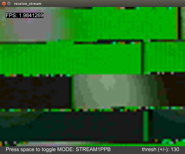
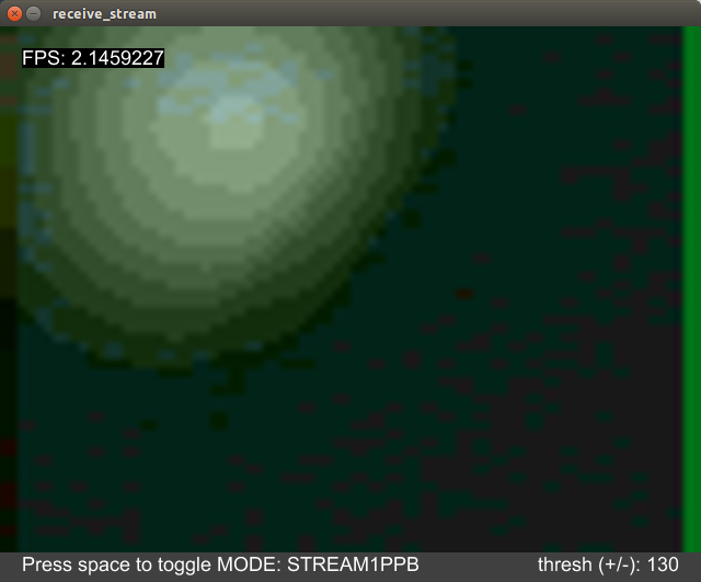
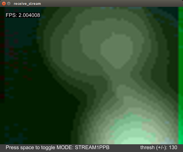
Luckily, the light blob detection from the Arduvision library worked. It refreshed at about 2-3 fps and displayed a light blob from lighting sources, such as the overhead light in the room or my mobile camera’s flash, and it displayed dark blobs when the light sources were covered. For some reason everything had a green-ish tinge.
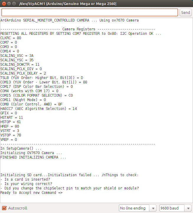
However, the code from the “Beginning OV7670 with Arduino” book did not work well. There were many problems (listed below in “Challenges”). The program could only take 1 picture at a time and save it to an SD card; it was unable to stream video. I tried to modify the code to output a video stream to Serial but did not succeed.
Below is the image quality from pictures taken with the book’s code. (In the right image, the dark blob on the lefthand side of the image is me!) As you can see it is quite blurry. I tried manually changing the focus, with little impact. The gain and other register settings were similar to the Arduvision library. I couldn’t figure out why it didn’t give me quality camera feed.


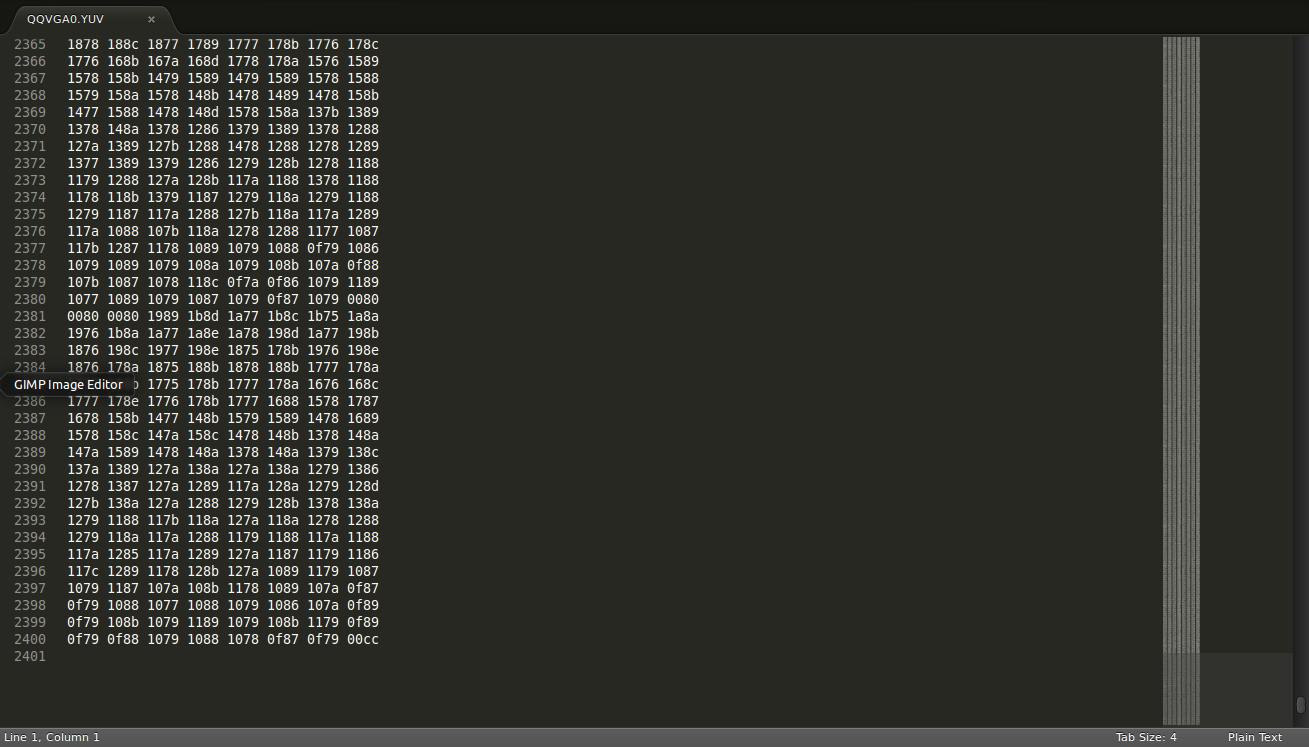
This was one of the blue images above, taken with the camera running the book code. It is a YUV-format image in QQVGA resolution that was saved to the SD card. It is 2400 lines. Each line has 8 “words,” with each word a 4-digit hexadecimal. Since 1 hex character is half a byte, each 4-hex “word” is 2 bytes.
2 bytes/word * 8 words/line * 2400 lines = 19200, which is the QQVGA resolution (120x160).
This confirms that each 2-byte “word” was actually a pixel, which is what I had set in the code.
Challenges
The biggest difficulty was that while I could get light blob detection to work, I couldn’t get clear image quality. I tried changing register settings, only reading luminance (black and white), rewriting the code, turning the camera focus knob, trying different code libraries, and switching cameras in case I had a bad camera, without success. I’m not sure why it didn’t work and why image quality was so blurry.
-
Be careful: Some libraries say “OV7670” in the name of the file, but you have to look at the code and description carefully. Some libraries titled “OV7670” are mislabeled and for other cameras, like OV7076, or other cameras starting with “OV.”
-
Although there are OV7670 cameras with different pin numbers, from 18-24, they seem to all use the same data sheet. If you use anything other than the 24-pin camera, it can seem confusing, but you can just ignore the extra pins.
-
One potential problem to be noted is that while the speed from the camera, I2C, and microprocessor clock cycles are fine, the baud rate for Serial transmission to PC may be too high.
-
From the Arduvision blog:
-
In the Arduino code, change the line “static const unsigned long _BAUDRATE = 500000;”
-
In the globalDefinitions.java file of the Processing sketch, change the line “public final static int BAUDRATE = 500000;”
-
Try with substituting the 500000 for 115200.
-
-
Some Arduinos are 3.3V while others are 5V. I thought I could use a 5V Arduino and just power the camera with the 3V3 pin. However, I2C on a 5V Arduino still uses 5V, and low from the Arduino can still pull the camera pins to high, or high from the camera can still be read as low to the Arduino. I used 4.7K pull-up resistors for this Arduino.
-
I read online that using 5V power may burn the image sensors, so just in case I accidentally had done that, I switched with Athulya’s camera. But it made no difference in image quality.
-
Some pins are pull-LOW to activate, while others are pull-HIGH to turn on. This is documented in the code libraries, but could be tricky if one is writing the code from scratch and did not notice the difference.
-
If you’re writing the registers from scratch, the register “0xB0” is listed as “Reserved” in the OV7670 reference documentation. However, an addendum document “OV7670 Software Application Note” specifies that this undocumented register should be set to the value “0x84” for YCbCr.
-
I solved some other funny SD card problems. The sample Arduino SD sketch wouldn’t run, so I tried using shorter wires between the SD card reader and the Arduino, and reformatting the 4GB SD card with FAT32, which allowed the sketch to run. But sometimes the SD card was taking 70 seconds to write one image, then 0 seconds for 2 following images; sometimes it re-wrote over old images. It turned out my SD card reader was somewhat broken/fragile, so I used a rubber band to hold it together.
-
Another problem was that the book code was too large to fit on an Arduino Nano clone, so I had to switch Arduinos to the Mega 2560 that the book originally listed.
-
My cheap Arduino Mega 2560 clone failed to compile and kept giving me firmware errors. From online advice, I could reinstall the Arduino firmware with dfu-programmer, but decided to just borrow my friend’s authentic Mega 2560.
-
For fun, I used a Particle Photon (basically a WiFi-enabled Arduino) with the camera as well, and was not able to get anything, not even debugging print statements. There is a bug with the Photon where I2C pulled low will not reset itself, which causes the status of the Photon to be stuck, always blinking its green LED. It can’t seem to do anything in this mode - unable to flash new programs or even connect to the Internet or Serial. To solve the I2C issue, I manually pulled up the Photon I2C pins by holding wires connected to 3V3 to both Photon I2C pins, rebooting the Photon to Safe Mode.
-
When YUV-format images were finally pulled from the SD card, we tried many different software and online apps to read the YUV file format. We finally used a 15-day free trial of software called “All to Real Converter Standard” to convert the images to JPG. This was the only one that worked, and it was not very convenient. Afterward we learned that FFMPEG could do this conversion as well.
Sources
(1) Beginning Arduino with OV7670 book http://psycho-sphere.com/ (The code can be found halfway down the page and downloaded as a zip)
(2) Arduvision library https://github.com/dasaki/arduvision and theRandomLab blog post where it’s from, which has an extensive list of other links
(3) OV7670 Datasheet downloads as PDF
(4) Electrodragon background info and description of the OV7670 camera http://www.electrodragon.com/w/index.php?title=OV7670_Module#Demo_Code
(5) arndtjenssen GitHub library with AVR ATmega1284, to give ideas on how to use it https://github.com/arndtjenssen/ov7670. An example of pin wirings for the ATMega1284
(6) Several posts on this ThinkSmallThings blog can give you an idea on how to use it https://thinksmallthings.wordpress.com/2015/01/11/atmega328-ov7670-fifo-module-software/
(7) Video resources with the OV7670 that may help http://www.yourepeat.com/g/OV7670
(8) More information on image formats: http://embeddedprogrammer.blogspot.com.es/2012/07/hacking-ov7670-camera-module-sccb-cheat.html
(9) GitHub code for OV7670, non-FIFO version: https://github.com/eranws/ov7670-no-ram-arduino-uno. This is based on ComputerNerd’s library
(10) Another OV7670 register library: https://github.com/dalmirdasilva/ArduinoCamera/tree/master/CameraOV7670
(11) Another register library, from Japan; haven’t used it: http://www.suwa-koubou.jp/micom/NetCamera/ov7670.c
(12) A register library. Has drivers for other OV cameras too. https://stuff.mit.edu/afs/sipb/contrib/linux/drivers/media/i2c/ov7670.c